PRODUCT
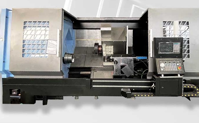
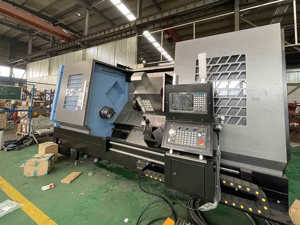
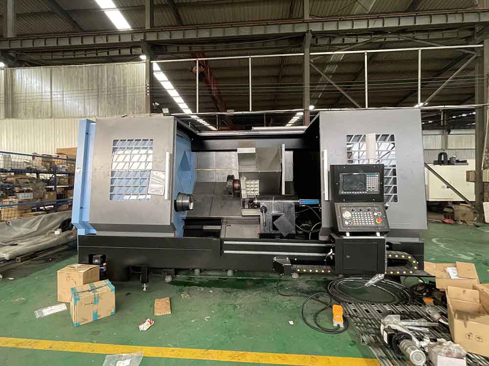
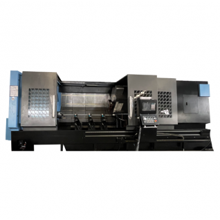
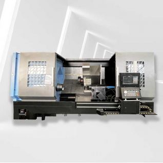
TCK700DY CNC Turning and Milling Compound Machine
The TCK700DY is a CNC turning and milling compound machine: a slant-bed lathe with driven tools that also mills, drills and taps in the same clamping. It swings Φ780 mm over the bed, machines up to Φ500 mm on the tool post, runs to 3000 rpm through a Φ132 mm spindle bore that takes Φ115 mm bar, and is built in four machining lengths from 1000 to 3000 mm. Overseas after-sales service and CE certified.
TCK700DY CNC Turning and Milling Compound Machine
The TCK700DY is a turning and milling compound machine. It is not a lathe with an extra axis bolted on: the tool turret carries driven tools, so milling cutters, drills and taps work on the same part that is being turned, in the same clamping, on the same datum. A shaft that needs a turned diameter, a milled flat, a cross hole and a tapped port leaves the machine finished instead of moving to a machining centre for a second set-up. The machine swings Φ780 mm over the bed, machines up to Φ500 mm on the tool post, runs to 3000 rpm through a Φ132 mm spindle bore, and is built in four machining lengths of 1000, 1500, 2000 and 3000 mm.
Key Features
- Turning and milling in one clamping, with driven tools on the turret
- Max. swing over bed Φ780 mm; max. machining diameter on tool post Φ500 mm
- Four machining lengths: 1000 / 1500 / 2000 / 3000 mm
- Spindle max. speed 3000 rpm
- Spindle bore Φ132 mm; bar stock diameter Φ115 mm
- X axis travel 350 + 20 mm; Z axis travel 1050 / 1650 / 2100 / 3100 mm
- Machine dimensions 7500 × 2300 × 2550 mm
- Machine weight 11500 / 12300 kg depending on length
- Suited to shafts, discs, flanges, valve bodies and automotive parts
Turning and Milling in One Set-Up
Every re-clamping of a part introduces a new error. The part settles onto the jaws, the centre line moves by a few hundredths, and a hole drilled after re-clamping no longer sits where it was programmed relative to the diameter turned before it. On a compound machine that error is removed at the source: the part is turned, the flat is milled, the cross hole is drilled and the thread is tapped before the jaws are opened. For a shaft with a milled keyway and a cross hole at a defined angle, this is the difference between a part that assembles and a part that has to be re-indicated on a second machine. It also shortens the route: one machine, one operator, one programme, instead of a lathe queue followed by a milling queue.
Φ780 mm Swing and Φ500 mm on the Tool Post
These two numbers are often read as if they were the same thing. They are not. Φ780 mm is the maximum swing over the bed: the largest diameter that can rotate without touching anything, measured with no tool in position. Φ500 mm is the maximum diameter that can actually be machined on the tool post, because once a tool holder and a turret station are in the cut, the space between the part and the tool is what limits the work. The gap between the two figures is 280 mm in diameter, or 140 mm in radius, and that is the space the tooling occupies. In practice: a disc of Φ600 mm will rotate on this machine but cannot be turned on its full diameter in one pass, because the tool post is limited to Φ500 mm. If your part is between Φ500 and Φ780 mm, send the drawing and the operation sequence, and we will confirm which diameters can be machined and where a second operation is needed, rather than leaving you to discover it after the machine is installed.
Four Machining Lengths: 1000, 1500, 2000 and 3000 mm
The 1000 / 1500 / 2000 / 3000 mm figure is not a telescopic bed. It is four build lengths of the same machine series, and the Z axis travel follows the same ladder: 1050, 1650, 2100 and 3100 mm, each about 50 mm longer than the machining length so the tool can enter and leave the cut. A customer who needs 2000 mm of machined length orders the 2000 mm build, not the 3000 mm machine with a shorter part. This matters for three reasons: price, floor space and weight. The dimensions in the table, 7500 × 2300 × 2550 mm, and the weight, 11500 to 12300 kg, refer to the longer builds; a 1000 mm machine is shorter and lighter. Confirm the length at the quotation stage, because the bed, the guideways, the ball screw and the tailstock arrangement all change with it.
Φ132 mm Spindle Bore and Φ115 mm Bar Capacity
The spindle bore is Φ132 mm and the bar stock diameter is Φ115 mm. Unlike some catalogue sheets where the bar figure and the bore figure contradict each other, these two are consistent: Φ115 mm bar passes through a Φ132 mm bore with 17 mm of radial clearance, which is the space needed for the chuck jaws, the collet or the bar feeder collet. That means the machine can be fed with Φ115 mm bar and run unattended with a bar feeder, which is the normal way a compound machine is used for volume production of small shafts, fittings and inserts. If your bar is larger than Φ115 mm, it can still be chucked as a billet, but it cannot be fed through the spindle, and the process has to be planned as a chucking job rather than a bar job.
X 350 + 20 mm and Z Travel: What the Numbers Mean
The X axis is listed as 350 + 20 mm. The 350 mm is the main cross travel; the additional 20 mm is a extra margin beyond the nominal stroke. The source data does not state what that margin is used for on this model, so we do not invent an explanation: it may be over-travel for tool change clearance, or a mechanical allowance in the slide design. Treat 350 mm as the working cross travel and confirm the exact figure against the general arrangement drawing for your machine. Z travel is 1050, 1650, 2100 or 3100 mm depending on the build length, and it is the stroke that decides how long a shaft can be turned between centres. A part longer than the Z travel needs a steady rest, a second set-up, or a longer build, and that decision should be made on the drawing, not on the shop floor.
Driven Tools and What They Change
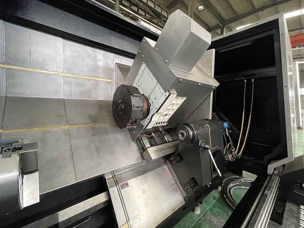
Driven tools turn the turret into a small milling head: a rotating tool holder is driven by the turret motor and can mill flats, mill slots, drill radial and axial holes, and tap, at programmed angles. On a plain lathe these operations are either done on a second machine or avoided in the part design. On the TCK700DY they are part of the turning programme. The practical result is fewer setups, shorter lead time and, more importantly, a part whose milled feature and turned diameter are tied to the same zero. The number of tool stations, the driven tool speed and the tool holder interface are configuration items: they are specified against the parts you actually make and confirmed in the quotation, because a shop that needs four driven stations and a shop that needs one are buying different machines.
Applications and Materials
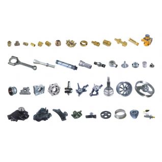
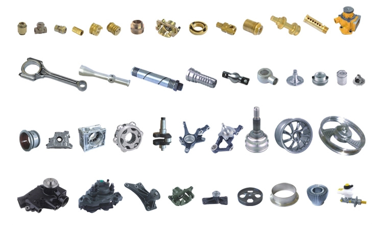
The TCK700DY is used for shafts, axle parts, discs, flanges, valve bodies, pipe fittings, hydraulic components, automotive parts and general machined components that combine a turned surface with a milled flat, a cross hole or a tapped port. Typical materials are carbon steel, alloy steel, stainless steel, cast iron, aluminium and copper alloys, with cutting data set by the material, the hardness, the fixture and the surface finish required. The machine is most valuable where the part needs more than one operation and the shop wants to keep it on one machine: it removes the transfer between lathe and machining centre, and with it the queue, the second fixture and the re-indicating error.
Technical Specifications
| Model | TCK700DY |
| Max. swing over bed | Φ780 mm |
| Max. machining diameter on tool post | Φ500 mm |
| Max. machining length | 1000 / 1500 / 2000 / 3000 mm |
| Spindle max. speed | 3000 rpm |
| Spindle bore | Φ132 mm |
| Bar stock diameter | Φ115 mm |
| X axis max. travel | 350 + 20 mm |
| Z axis max. travel | 1050 / 1650 / 2100 / 3100 mm |
| Machine dimensions (L × W × H) | 7500 × 2300 × 2550 mm |
| Machine weight | 11500 / 12300 kg |
Delivery, Installation and Service
The machine ships as a complete unit measuring 7500 × 2300 × 2550 mm and weighing 11500 to 12300 kg depending on the build length, so crane capacity, floor loading, door width and the route into the workshop should be checked before delivery is booked. Installation is supported with foundation and levelling guidance, commissioning checks and operator training on the control and on driven tool set-up. Spare parts and technical support are handled through our overseas after-sales service, and the machines are CE certified. Spindle power, turret station count, driven tool speed, tailstock type and control configuration are specified against the actual workpiece and process and confirmed in the quotation, rather than assumed from a generic catalogue list.
Request a Quote
Send us the part drawing, the material, the batch size and the operations you need, and we will confirm the TCK700DY build length, the turret and driven tool configuration, the work-holding, the price, the delivery time and the technical support. We provide overseas after-sales service and CE certified machines.